SimItemBlocks
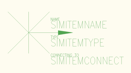
To represent 3D components within a CAD model, a marker called SimItemBlock is used to mark the key attributes of each 3D components. SimItemBlocks are generic AutoCAD blocks.

An example of a SimItemBlock is provided with Sym3 installation. It is possible to create your own SimItemBlock or use blocks that you currently use for your 3D equipment. See “Creating SimItemBlocks” for complete instructions.
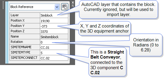
The SimItemBlock includes of four pieces of information:
- SimItemName attribute - used to define the name of the 3D component in the model
- SimItemType attribute - used to define the 3D component’s type
- SimItemConnect attribute - any connections to other items in the simulation
- Coordinates and orientation.

Each of the supported 3D components is marked by placing one or more SimItemBlocks on the actual equipment on the drawing. Refer to one of the following topics for marking instructions of each 3D component:
Tip: Place all SimItemBlock on a separate layer to easily show, hide and manipulate them.
Tip: Do NOT Mirror SimItemBlocks, the orientation will be incorrect. To use Rotate or manual rotate the block to its position.
Note: SimItemBlocks are always in coplanar to the X,Y plane.