Equipment: Path
 |
|
Description
A Path equipment allows a product to move along a path.
Creation
From the Toolbox, simply drag and drop a Path into the simulation.
Access
From the Project Explorer >System > Equipment > Path.
Or directly in the simulation.
Coordinates
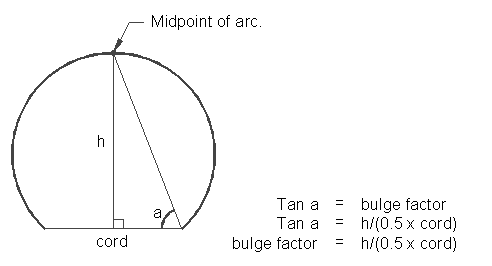
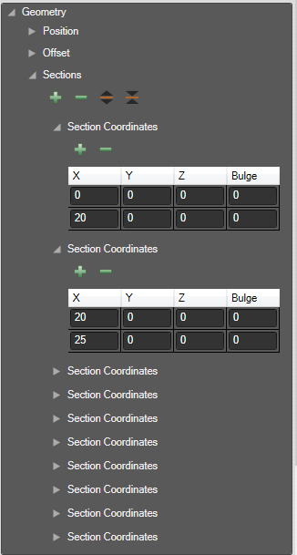
Each coordinate contains 4 values (X, Y, Z and Bulge). Adding a Bulge is for defining a part of the path where opposing objects can be configured to cross. The bulge formula is:

Coordinates of all sections are available in the Sections section of the properties.

Visual Modes
The path mode can be changed to:
- Quad (Default): In quad mode able to change the width of the path.

- Line: The line width cannot be changed.

- Rail: New render mode for the path Rail. The 2D path will change to 3D shape which extrude along it. When the mode changed to Rail, a new property will add in visual category as Height of the shape.

Properties
| Name | Description |
|---|---|
| Coordinates | List of coordinates. |
| Mode | Visual mode, can be:
|
| Line Width | Default = 0.1 (metres) Width of the line in the units chosen when the project was created. (metres or feet) |
| Double | New property in visual category of path as Double. When tick the double checkbox the single path will change to double path with a gap between it. The gap size can be adjustable. This property is available for Quad, Line and Rail mode. |