Concurrent Event Processing
Introduction
Usually Sym3 Integrator runs a simulation or emulation on a single CPU thread and all events that occur during the simulation or emulation run are processed one after the other. For very large systems it may be beneficial to split the system into smaller parts and process events for each sub-system on a separate thread to take advantage of today’s multi-core CPUs.
In Sym3 Integrator these separate threads are called ‘Logical Processors’.
At sub-system boundaries some communication between logical processors is required to ensure that subs-systems continue to work as a part of the whole system.
This document describes how to approach concurrent processing and how to develop script for communications across sub-systems.
Projects that benefit from concurrent processing
Not all projects benefit from concurrent processing because of overheads in logical processor scheduling and because all logical processors remain synchronized to real time and are therefore blocked from processing independently ‘too far ahead’.
Projects that are likely to benefit from concurrent processing are those that have CPU intensive event processing with evenly distributed loads for logical processors.
Projects that are unlikely to benefit from concurrent processing are those that have many light-weight events requiring little CPU usage per event.
Choosing a good sub-system separation
It is unlikely that there is benefit in running more logical processors than there are numbers of logical CPU cores on the executing machine. Because we do not know what machine is going to be used for a project, a suitable limit for the maximum number of logical processors may be the number of logical CPU cores found in ‘typical’ hardware. Currently a processor with eight logical cores may be considered ‘typical’ for demanding simulations and the maximum number of logical processors for a simulation project one may therefore aim for is eight.
This does not mean that one should use 8 logical processors in general. Use of logical processors comes with overheads and it is more important to find a good separation of sub-systems. A ‘good separation’ means that sub-systems are kept large and fairly evenly sized in terms of complexity with few touch points between them.
Creating logical processors
To create logical processors, go to the Project Explorer in the Sym3 Integrator main window, right click on the ‘Logical Processors’ folder and select ‘New’. Create as many logical processors as you intend to use. Logical processors can be named to reflect their purpose. The name should be chosen carefully as it is used to refer to the logical processor in script. A later name change may therefore also require to update script where the name is used. It may be suitable to simply keep the default name of ‘LogicalProcessor1’, ‘LogicalProcessor2’, and so forth.

Assigning logical processors to sub-system components
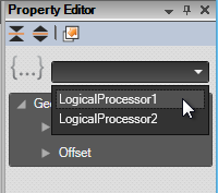
Consider assigning a layer to sub-systems belonging to the same logical processor, ensure that only the particular layer is visible in the graphical view and then use the box selection tool to select all sub-system components. You can also use the box selection tool to select multiple components independent of the assigned layer or pick single components for logical processor assignment. A combination of these approaches may be necessary to achieve the desired result.

After selecting components for logical processor assignment move to the Properties panel and select the desired Logical Processor for these components.

Clicking on a logical processor name within the Project Explorer selects and highlights all components that are assigned to that logical processor.
Assigning logical processors to devices
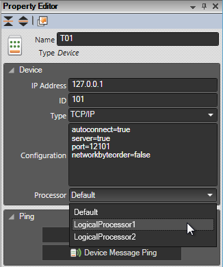
You can also assign logical processors to devices with the effect that messages received from these devices are processed on the logical processor thread. To assign a logical processor to a device select the device in the Project Explorer panel, then select the desired logical processor in the Property Editor.

Core concept of logical processors
Once a logical processor is assigned to a component or device any event or message that is processed on the logical processor thread is no longer allowed to directly affect components belonging to a different logical processor; these components become ‘invisible’ for other logical processors. For example, running a script function GetComponentByNameAndType may return a null result if the component exists but is assigned to a different logical processor. The only way to communicate between logical processors is via specific script functions that are introduced in a later section.
Each logical processor thread executes script on its own thread. The main event processor thread still begins script execution beginning with the script function OnSimulationStart. On the event processor thread all components are accessible but the objective of concurrent processing is to remove as much load as possible from the event processor to the logical processor threads. Further, subscriptions to component events must be executed on the assigned logical processor thread and will fail if attempted on the event processing thread (or a thread different from the assign logical processor thread). Use the event processor script for consolidation of statistics collected for the sub-systems and similar light weight tasks.
Logical processors begin their script execution with OnSimulationStart_$ProcessorName where $ProcessorName is a place holder for the chosen name of the logical processor. For example, ‘LogicalProcessor1’ begins script execution with script function OnSimulationStart_LogicalProcessor1, and ‘LogicalProcessor2’ begins script execution with script function OnSimulationStart_LogicalProcessor2, and so forth. In similar fashion logical processor specific OnSimulationStarting, OnSimulationStopping, and OnSimulationStopped are called.
While there are these specific entry points for logical processors, the same simulation script code is shared across all logical processors and you are free to arrange script in any suitable form. For example, scripting could be separated into sub-system (logical processor) specific parts and shared functions. Ideally, most of the script code is placed into shared functions and only small portions are logical processor specific. A new script function
GetExecutingLogicalProcessor();
returning the name of the logical processor currently executing the script may be used to conditionally execute script intended for a specific logical processor only, for example during initialisation. Further, the logical processor name assigned to a component is a property of the component. For example, the logical processor name of a component variable ‘conveyor1’ can be accessed like so:
conveyor1.LogicalProcessor;
Communicating across logical processors
Script functions
Unless sub-systems are completely isolated some communications is required between logical processors, for example, to transfer a product from one sub-system to the next. The following script function is available to facilitate such communications:
SendToLogicalProcessor (logicalProcessorName, functionName, arg1, arg2, …);
This sends a number of arguments to the script function with the given function name executing on the logical processer thread identified by the logical processor name. Arguments must be of a supported type, either a numerical value, a string, an object containing these types, or a component reference (equipment). Example:
SendToLogicalProcessor(
    "LogicalProcessor2",
    "OnTransferFromConveyorBoundary",
    nextName,
    product
);
There is also a script function to send messages to the event processor thread:
SendToMainProcessor (functionName, arg1, arg2, …);
This sends a number of arguments to the script function with the given function name executing on the event processor thread. Arguments must be of a supported type, either a numerical value, a string, an object containing these types, or a component reference (equipment). Example:
SendToMainProcessor("OnProcessProduct", productBarcode);
Example 1
In this example Chutes (as exits of a cross belt sorter) have been chosen as sub-system boundaries. Each chute is assigned to the same logical processor as the cross belt sorter which means that the transfer of product from the cross belt sorter onto the chute works just like in a single threaded system. The conveyor following the chute, however, is assigned to a different logical processor and without further interaction the product would simply disappear when it leaves the chute. To prevent this from happening and transfer the product onto the conveyor and the next logical processor the following script code is implemented.
On the chute’s logical processor thread the OnProductRemoved is subscribed to:
SubscribeToEvent(
    "OnProductRemoved",
    chuteName,
    "Chute",
    OnProductRemovedAtBoundary
);
The OnProductRemovedAtBoundary function is called when a product reaches the end of the chute and is about to be removed. The function sends a message to the conveyors logical processor:
function OnProductRemovedAtBoundary(sender, product)
{
    // get name of exit transporter
    var boundaryChute = "ChuteExit1";

    // assigning a different logical processor here will
    // keep the product alive for the next logical processor
     product.AssignToLogicalProcessor("LogicalProcessor2");

    // call function on other processor
    SendToLogicalProcessor("LogicalProcessor2", "OnTransferFromBoundary", boundaryChute, product);
}
Finally, the OnTransferFromBoundary function is executed on the next logical processor. This function simply moves the product onto the targeted conveyor.
function OnTransferFromBoundary(targetName, product) {

    MoveProduct(product, targetName, 0 /distance/);
}
The product now continues being transported on the conveyor controlled by its logical processor.
Example 2
In this example two cascading conveyors are chosen as a system boundary. The first conveyor in the sequence is referred to as the ‘preceding’ conveyor and the following conveyor as the ‘next’ conveyor. Because different logical processors are assigned to the conveyors the cascading logic no longer works; it needs to be implemented in script via the exchange of messages. Note that some data preparation storing information about the boundary conveyors is omitted from this example.
For the preceding conveyor the OnProductRemoved and OnProductBlocking events are processed:
// this conveyor needs to be monitored for cascade start stop
SubscribeToEvent("OnProductRemoved", conveyorName, "Conveyor", OnProductRemovedAtBoundaryConveyor);

var pe = conveyor.PESensors[0];
SubscribeToEvent("OnProductBlocking", pe.Name, "PE Sensor", OnProductBlockingAtBoundaryConveyor);
Similarly to the previous example, the OnProductRemovedAtBoundaryConveyor sends a message to the next logical processor to continue transporting the product.
function OnProductRemovedAtBoundaryConveyor(sender, product)
{
    var boundaryConveyor = "Conveyor2";

    // assigning a different logical processor here will
    // keep the product alive for the next logical processor
    product.AssignToLogicalProcessor("LogicalProcessor2");

    SendToLogicalProcessor("LogicalProcessor2", "OnTransferFromBoundaryConveyor", boundaryConveyor.nextName, product);
}
The OnProductBlockingAtBoundaryConveyor event stops the preceding conveyor if the shouldCascadeStop flag is set (see below how the flags is set).
function OnProductBlockingAtBoundaryConveyor(sender, product)
{
    var prevConv = sender.Parent;
    var boundaryConveyor = prevBoundaryConveyors[prevConv.Name];
    if (boundaryConveyor.shouldCascadeStop)
        prevConv.Running = false;
}
For the next conveyor the OnConveyorRunningStateChange event is monitored:
SubscribeToEvent("OnConveyorRunningStateChange", conveyorName, "Conveyor", OnNextBoundaryConveyorStartStop);
The OnNextBoundaryConveyorStartStop event processing either sends a delayed ‘start’ message to the preceding conveyor (emulating a cascading start delay) or sends a ‘stop’ message immediately.
function OnNextBoundaryConveyorStartStop(sender) {

    var bc = nextBoundaryConveyors[sender.Name];
    if (sender.Running) {
        // cascade delay
        SetTimerEx(bc.id, 500, OnNextBoundaryConveyorCascadeStart, bc);
    } else {
        SendToLogicalProcessor(bc.prevLogicalProcessor, "OnNextBoundaryConveyorHasStopped", bc.prevName);
    }
}
The OnNextBoundaryConveyorCascadeStart function is still executed on the next conveyor’s logical processor thread. The function checks if the conveyor is still running and if that is the case then a message is sent to the previous logical processor to start the preceding conveyor.
function OnNextBoundaryConveyorCascadeStart(Id, bc)
    {
    if (bc.conveyor.Running) {

        // still running; start prev conveyor
        SendToLogicalProcessor(bc.prevLogicalProcessor, "OnNextBoundaryConveyorHasStarted", bc.prevName);
    }
}
The OnNextBoundaryConveyorHasStopped function executes on the preceding conveyor’s logical processor thread. Here the shouldCascadeStop flag is set so that the preceding conveyor is stopped if or when the photo eye at the end of the preceding conveyor is blocked.
function OnNextBoundaryConveyorHasStopped(prevName)
    {
    var bc = prevBoundaryConveyors[prevName];
    bc.shouldCascadeStop = true;
    var pe = bc.conveyor.PESensors[0];
    if (pe.Blocked) {
        bc.conveyor.Running = false;
    }
}
When the previous logical processor receives the OnNextBoundaryConveyorHasStarted message for the preceding conveyor then its state also changes to ‘running’:
function OnNextBoundaryConveyorHasStarted(prevName)
{
    var bc = prevBoundaryConveyors[prevName];
    bc.shouldCascadeStop = false;
    bc.conveyor.Running = true;
}
Finally, as before, the OnTransferFromBoundaryConveyor function executed on the next conveyor’s logical processor thread places the product onto the target conveyor.
function OnTransferFromBoundaryConveyor(targetName, product) {
    MoveProduct(product, targetName, 0);
}
Conclusion
Implementing script for cross-logical-processor communications can be more or less complex depending on the chosen system boundaries and the demands on acceptable accuracy.
Reporting
While processing concurrently key data has to be collected per logical processor sub-system and consolidated for final reporting. Consolidation can take place by, for example, sending a message to the main thread (using method SendToMainThread) in regular intervals or by storing information into system properties on the logical processor thread and then summarising those values on the event processor thread periodically. System properties can be accessed from any thread.
Measuring Logical Processor Performance
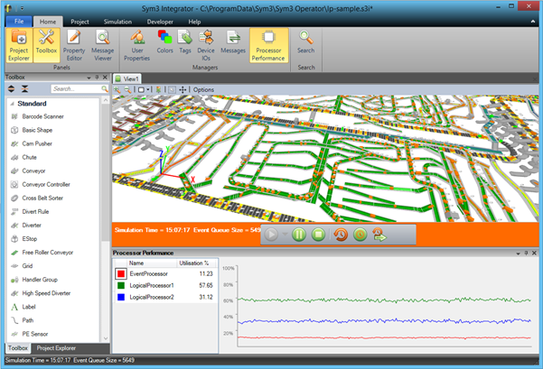
Sym3 Integrator provides a performance chart to assist in judging logical processor utilisation. Ideally the event processor thread is used very little and other processors are utilised evenly. The performance chart panel is shown by clicking on the ‘Processor Performance’ button in the ‘Home’ tab:

The chart is displayed in a panel that may be docked within the main window. It shows the proportional logical processor utilisation.

The performance chart shown above indicates that LogicalProcessor1 is utilised about twice as much as LogicalProcessor2. The system could therefore be more balanced if more components were assigned to LogicalProcessor2, however, this is not always practical if it involves more elaborate scripting.
Limitations
Because of latencies introduced by the way logical processors operate in Sym3 Integrator it is recommended to only run concurrent simulation or emulation in real-time. Running faster than real-time is still possible at the cost of reducing accuracy with increasing time factors. The ‘Run through’ option is unavailable while simulating or emulating concurrently. An attempt to ‘run through’ will result in the time factor to be reset to one.
If Sym3 Integrator detects that the system cannot cope with the amount of events scheduled concurrently while running faster than real-time, Sym3 Integrator will also reset the time factor back to one.