Data Source Emulation: Mitsubishi
Sym3 can simulate the address space of Mitsubishi MELSEC L and Q series PLCs. Another PLC can access Sym3 Tags by using MC Protocol addresses.
Sym3 only reponds to Device Access Batch Read (0x0401) and Batch Write commands for Word Unit addressing.
Create a new Data Source
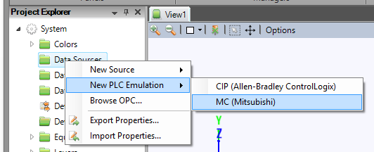
A Data Source can be defined in Sym3, right click on Project Explorer > Data Sources then select ‘MC (Mitsubishi)’ from the ‘New PLC Emulation’ menu.
Select the newly created Data Source and in the Property Editor and rename as necessary.
You can specify the IP Address and Port number Sym3 will be listening to (Any port value from 1 to 65535). Default port is 4600 and Default IP is empty, and an empty IP means that it will listens on all network adapters.
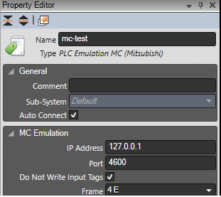
You can specify which message format to use when communicating with the MC PLC Emulation. Sym3 support’s Frame 3E and 4E. The MC PLC emulation itself supports both by interpreting the incoming message header (0x0050u or 0x0054u) and responds accordingly.
Do Not Write Input Tags is an Integrator-only flag on the Mitsubishi data source that defaults to off.
When enabled, that data source will only write the output tags changes to its device memory.
Adding a MC Tag
Click on the Property Editor option in the Ribbon bar to open the Property Editor Panel.
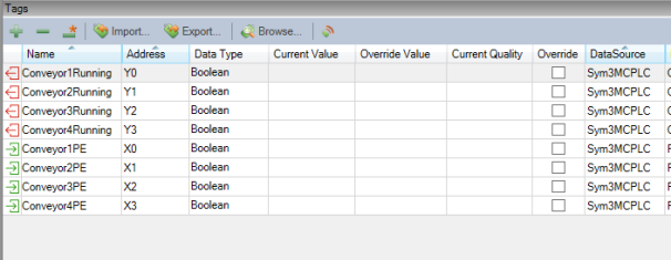
Create Tags in the Tag Manager Window using the + button.
Enter a Name for the Tag in Sym3 and the Data Source for the Tag.
A Data Type must be entered for the Tag.
The Tag Address is the MELSEC Device Address as used on a MELSEC L / Q Series PLC.
See MELSEC-L CPU Module User’s Manual (Built-In Ethernet Function) and MELSEC-Q CPU Module User’s Manual (Built-In Ethernet Function).
The Address is the combination of a 1 to 3 character alphabetic Device Code mnemonic and the numeric address of the Device Point.
By Mitsubishi’s convention, numerical device point addresses are specified in either decimal or hexadecimal radix, specified individually by device with no particular pattern as to which devices use which radix. Further, hexadecimal addresses are not explicitly identified as being hex in the notation (i.e. a leading 0x or trailing H) although hexadecimal addresses with a leading digit of A-F must have a leading 0 prepended.
Example
- X10 – Device X, device point sixteen
- M10 – Device M, device point ten
- X0A – Device X, device point ten
The table below lists the device codes, type and address radix for the devices supported by the MC data source.
| Device Name | Code | Type | Radix |
|---|---|---|---|
| Special relay | SM | Bit | Decimal |
| Special register | SD | Word | Decimal |
| Input | X | Bit | Hexadecimal |
| Output | Y | Bit | Hexadecimal |
| Internal relay | M | Bit | Decimal |
| Latch relay | L | Bit | Decimal |
| Annunciator | F | Bit | Decimal |
| Edge relay | V | Bit | Decimal |
| Link relay | B | Bit | Hexadecimal |
| Data register | D | Word | Decimal |
| Link register | W | Word | Hexadecimal |
| Timer Contact | TS | Bit | Decimal |
| Timer Coil | TC | Bit | Decimal |
| Timer Current Value | TN | Word | Decimal |
| Retentive Timer Contact | STS | Bit | Decimal |
| Retentive Timer Coil | STC | Bit | Decimal |
| Retentive Timer Current value | STN | Word | Decimal |
| Counter Contact | CS | Bit | Decimal |
| Counter Coil | CC | Bit | Decimal |
| Counter Current value | CN | Word | Decimal |
| Link special relay | SB | Bit | Hexadecimal |
| Link special register | SW | Word | Hexadecimal |
| Direct access input | DX | Bit | Hexadecimal |
| Direct access output | DY | Bit | Hexadecimal |
| Index register | Z | Word | Decimal |
| File register - Block switching method | R | Word | Decimal |
| File register - Serial number access method | ZR | Word | Hexadecimal |